
Measurement Tab
Qosium offers a wide selection of parameters for configuring how measurements are performed. In Qosium Scope, these parameters are configured in the measurement tab.
1. Overview #
This tab consists of the following settings groups. Detailed information on each group can be found in the following sections.
- Packet Capture Settings
- Measurement Settings
- Control Connection Settings - Visible when advanced settings are enabled
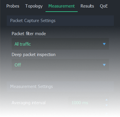
2. Packet Capture Settings #
This group contains settings on how packets are captured and identified.
2.1. Packet Filter Mode #
Packet filter mode determines how packets are filtered. In other words, packets that meet the given filter criteria contribute to the measurement results. The available options depend on current settings. For more information, see Packet Filters in Qosium.
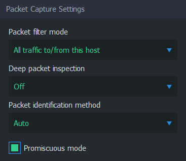
The first option in the list is an automatic mode. The name and function of this setting depend on whether a single-point or two-point measurement is selected:
- In a single-point measurement, this option is named All IP traffic to/from this host. Only (IPv4 or IPv6) traffic originating from or targetted to the measurement point is captured.
- In a two-point measurement, this option is named All IP traffic between hosts. Only (IPv4 or IPv6) traffic that is generated by the measurement points and is targeted to the other measurement point is captured.
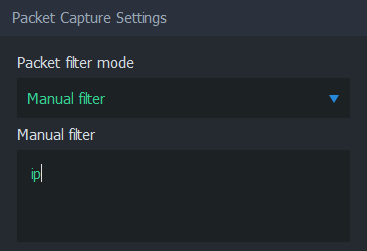
The second option in this list is Manual filter. When selected, a text field appears below, where an arbitrary packet filter can be typed manually.
Regardless of the choices made, the final filter applied to the measurement can be seen on Status Tab once the measurement is started.
2.2. Secondary Probe Filter Mode #
 Visible when two-point measurement, NAT between Probes, and manual filter are selected
Secondary Probe Filter Mode determines how the given manual packet filter is treated in the secondary Probe. Setting this option is relevant only if NAT occurs on the measurement path. For more information, see How to Measure over NAT.
- Equal filter (default) - The same filter as to the primary Probe is set to the secondary.
- Strict autofilter - The filter is composed automatically based on what kind of flow the primary Probe with its filter observes. The IPv4 addresses, protocol, and ports (when they exist) are included in the filter. Thus, this filter is strict in the sense that only a single flow will fit it.
- Loose autofilter - Similar to Strict autofilter, but only the IPv4 addresses of the flow are included in the filter. The filter is loose in the sense that multiple flows will fit that.
2.3. Deep Packet Inspection #
Available only in single-point measurementsTwo measurement points are always required to perform a QoS measurement. However, some protocols themselves carry information from the other end, allowing QoS calculations to be made by a single Qosium Probe. Thus, this is still a two-point measurement, but now there is no Probe in the other end. Instead, the application/service acts as the secondary measurement point, providing valid information and enabling QoS calculation.
Qosium currently supports two protocols for this kind of deep packet inspection: RTP and MPEG-2 (TS). These methods enable packet loss statistic calculation by a single Qosium Probe. Please note that this QoS calculation can be done for received traffic only as there is no feedback channel for the sent traffic.
- RTP - Use RTP protocol header information.
- MPEG-2 (TS) - Use MPEG-2 Transport stream header information.
 The measured traffic stream must be of the selected type. Otherwise, the DPI-based QoS calculations cannot be made.
2.4. Packet Identification Method #
Visible when advanced settings are enabled.The packet identification method defines how Qosium identifies packets between measurement points. Thus, the meaning of this is important under a two-point measurement and not that much in a single-point measurement. This is one of the parameters that you generally do not need to touch since the default automatic setting will handle most of the measurement cases. However, if you do need to set this manually, here are the options and their explanations.
- Auto (default) - Qosium selects the method from the options below based on the measurement scenario. The selection is made safely, i.e., a method typically known to function in most of the cases in a similar scenario is selected. This might not always be the optimal method.
- IPv4 ID Field - Qosium uses the Identification field in the IPv4 header for packet identification. Naturally, the first requirement for this to work is that the measured traffic shall be of IPv4 type. A second requirement is that the measured stream is using the IPv4 Identification field as specified. This is not always the case, but luckily the non-standard usage is rare. A restriction lies in the fact that the Identification field has only 16 bits, limiting the available unique numbering per time instance to 65536. Thus, if you are using a 1 s averaging interval, your measurement should be working fine, as long as the target measurement stream’s packet rate is clearly less than this (e.g., < 30000 pkts/s). Beyond that, QoS calculation is not guaranteed to be entirely accurate. Then, if you are using a longer averaging interval, e.g., 10 s, the safe packet rate drops to one-tenth of the previous, accordingly.
- RTP Sequence Number - Qosium uses the Sequence number field in the RTP header for packet identification. This lightweight option is ideal for measuring RTP streams. But, be aware that while Qosium checks that there is room in the packet for the RTP header, it does not check its actual existence. Thus, setting this option with non-RTP traffic can result in unpredictable behavior.
- Payload-Based ID - Qosium calculates the identification based on the packet payload. This method is not dependent on the protocol headers, so it works for IP packets and pure L2 (e.g., Ethernet) packets. If a packet has no payload, IP4 ID Field, when present, is used.
- Extended Payload-Based ID - Qosium calculates the identification based on the packet payload, including some parts of the transport layer header. This can be your choice if the measured traffic stream is composed of, e.g., very short packets or packets with duplicated data in their payloads. However, if your NIC is using offloading methods, this method might not always work correctly.
- Pure Payload-Based ID - This is a very similar method with Payload-Based ID, but packets without payload are just ignored from QoS calculation. In many ways, this is the most robust identification method. However, the drawback, as with all the payload-based methods, is that if the payloads between packets have little or no variation, QoS calculation might not always be accurate.
- NAT bypasser + Payload based ID - Operates as Payload-Based ID but with NAT bypasser functionality enabled. NAT bypasser lets you perform a passive measurement in a scenario where there is a NAT between the measurement points.
- NAT Bypasser + Pure Payload Based ID - Operates as Pure Payload-Based ID but with NAT bypasser functionality enabled.
2.5. Promiscuous Mode #
Visible when advanced settings are enabled.Promiscuous ModePromiscuous Mode
A mode in network interfaces, which allows packet sniffers to process packets even if they are not designated to said network interface. allows Qosium to capture packets that are not designated to the network card performing the capture. This is a fairly common case with Qosium, and it’s recommended to leave this option enabled unless there’s a specific reason to disable it. Some network cards might not support promiscuous mode, which is an example of such a specific reason.
3. Measurement Settings #
Measurement settings contribute to the way how measurement results are gathered and interpreted.
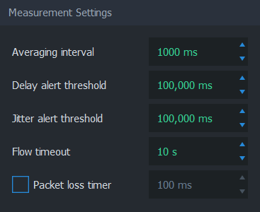
3.1. Averaging Interval #
As the name implies, this parameter defines the time interval each average sample represents. Coincidentally, averaging interval also determines how often Scope receives average results.
3.2. Delay Alert Threshold #
Packets with a delay above this threshold are counted in QoS Statistics: Th. ex. delay pkts. This statistic provides a way to understand the number of highly delayed single packets without actual packet-level statistics.
3.3. Jitter Alert Threshold #
Packets with a jitter above this threshold are counted in QoS Statistics: Th. ex. jitter pkts. This statistic provides a way to understand the number of single packets with high jitter without going to the actual packet-level statistics.
3.4. Flow Timeout #
Visible when advanced settings are enabled.Flow timeout determines the duration in which a flow remains in the flow map after the most recent packet belonging to the flow has been registered.
Ideally, this value should be set as small as possible. However, if packets are arriving sporadically, flows may disappear from the flow map too early. This results in flows disappearing and re-appearing, as Scope deems these flows terminated prematurely. To counter this phenomenon, increase the flow timeout. As a result, the correct value is always somewhat dependent on the traffic flows’ properties to be measured.
3.5. Packet Loss Timer #
Visible when advanced settings are enabled.Packet Loss TimerPacket Loss Timer
Qosium determines packet losses by waiting each packet a predefined amount of time. Packet loss timer defines this duration. determines the duration used to determine packet losses. Setting this parameter is always a compromise between reactivity and the capability to detect long delays. If not enabled, Qosium automatically sets a generally well-functioning value for this parameter. The final value can be seen on the Status Tab during the measurement.
4. Control Connection Settings #
Visible when advanced settings are enabled.These settings are related to the QMCP connections between Qosium Products (e.g., from Scope to primary Probe to external Listener and Secondary Probe). Adjusting these settings is not typically needed.
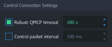
4.1. Robust QMCP Timeout #
This parameter is for toggling Robust QMCP ModeRobust QMCP Mode
A feature which allows Qosium products to re-connect each other and carry on the measurement, even if connectivity is momentarily lost. on/off and for adjusting the duration of how long reconnection is tried before giving up. This is especially useful when measuring over a weak, unreliable network path.
Set this value according to your needs. Very large values are ideal while carrying out long-term monitoring, while small values are recommended for carrying out short measurement campaigns.
4.2. Control Packet Interval #
This parameter affects the control packet interval between the Qosium Probes in a two-point measurement. It is recommended to leave this option unchecked to allow Qosium to calculate an optimal value automatically instead. The final value can be seen on the Status Tab.
Glossary >
Promiscuous Mode
A mode in network interfaces, which allows packet sniffers to process packets even if they are not designated to said network interface.
This mode is essential in Qosium, since it’s fairly common to measure network traffic by placing Probes somewhere in-path or off-path via port mirroring instead of end-points.
Some network interfaces do not support promiscuous mode, so try turning it off if starting measurement results in an error, or no packets are captured.
For more information, see the Wikipedia article on Promiscuous mode.
Packet Loss Timer
Qosium determines packet losses by waiting each packet a predefined amount of time. Packet loss timer defines this duration.
If this value is set too small, packets exceeding this duration in the traversal of the measurement path will be incorrectly considered lost. A large value yields more precise results, but causes a lag to the reporting of lost packets, since Qosium needs to wait for this duration for packets before reporting them as lost.
Loss timer should be always at least 2 × control packet interval. The latter parameter is typically set automatically according to the averaging interval, but it can be also changed manually. In order to have short packet loss timer value, set the control packet interval as well.
Robust QMCP Mode
A feature which allows Qosium products to re-connect each other and carry on the measurement, even if connectivity is momentarily lost.
If robust QMCP mode is not enabled, the measurement is stopped if the connection between Qosium products is lost. It is recommended to keep this feature always on unless there’s a good reason to disable it.