
Understanding Measurement Topology
Where to install measurement agents and measurement controllers, what can be measured, how to set the parameters, etc. That is what understanding measurement topology is all about. It is one of the key things regarding QoS measurements.
Contents
1. To Start with #
Measurement topology is something that deals with almost everything related to the Qosium measurement setup, including at least the following:
- The traffic to be measured and its directions
- Measurement nodes, their network interfaces, and other network devices involved
- Measurement software installations
- Measurement parameters
Thus, mastering the measurement topology is essential. To get started with Qosium measurements, consider the following:
- What application or service is the interesting one? Or are there, perhaps, multiple interesting flows or all traffic at some point in the network?
- This is the key to everything in the measurement setup.
- This also directly affects the packet filter to be set.
- Are you interested in full QoS results, or are traffic statistics (or just packet captures) enough?
- Full QoS results mean that there will be two measurement points required.
- Where does the interesting traffic flow? What is the path or place of your interest for measuring this traffic?
- Set the measurement points in such a way that the interesting path or place will be included. If just possible, install Qosium Probes directly to these points. If not, install them as near as possible. Another way is to mirror the traffic to be measured to an external device on which Qosium Probe runs.
- How are the Qosium Probe installations selected for the measurement located from the perspective of the application traffic you intend to measure (end-points, middle-points, external devices)?
- Set the placement parameters accordingly.
- Through which network interfaces the interesting traffic flows in the measurement points?
- Set the capture interfaces of the measurement points accordingly.
- If a two-point measurement, is there a NATNetwork Address Translation
A technique for remapping an IP address space somewhere between the measurement points (a two-point measurement)?- If so, this requires special attention in parameterization.
In the next section, we go through typical topology models.
2. Typical Topology Models #
This section presents some general topology types. Please note that often, in reality, the topologies can be much more complex. However, even complex topologies typically resemble one of these at a logical level. In the presented measurement topologies, we focus only on two-point measurement cases.
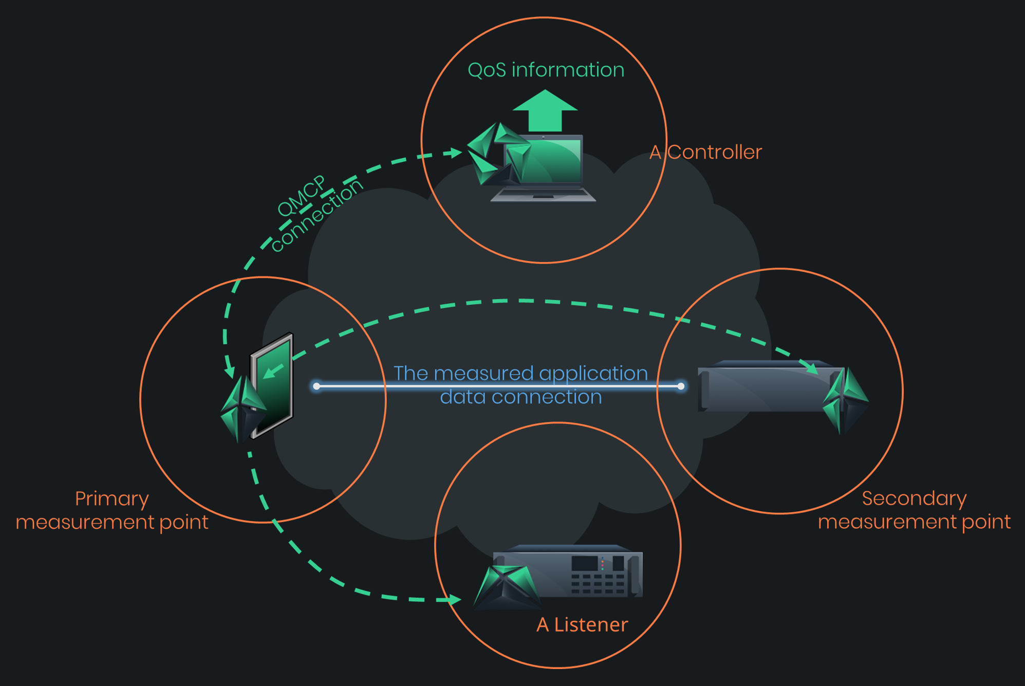
A general two-point Qosium measurement with the QMCPQoS Measurement Control Protocol
Kaitotek’s proprietary protocol for controlling measurements and gathering measurement results. flows, including a listener, is shown in the figure below. You can select the measurement controller’s location (e.g., Qosium Scope, Scopemon) quite freely. However, you should still consider the QMCP traffic flow orientation: they are chained, as seen in the figure below. The controller does not communicate directly with the Secondary measurement point but through the Primary. The optimal place in terms of minimizing the overhead is to run the controller in the Primary measurement point device. However, the QMCP connection between the controller and the Primary measurement point is very light-weight when measuring only average results and flow results. That is why the controller can very well be used remotely in a separate device, as illustrated in the figure.
2.1. End-to-End #
Are you interested in how your connected service works from the perspective of an end-user? The end-to-end topology reveals that.
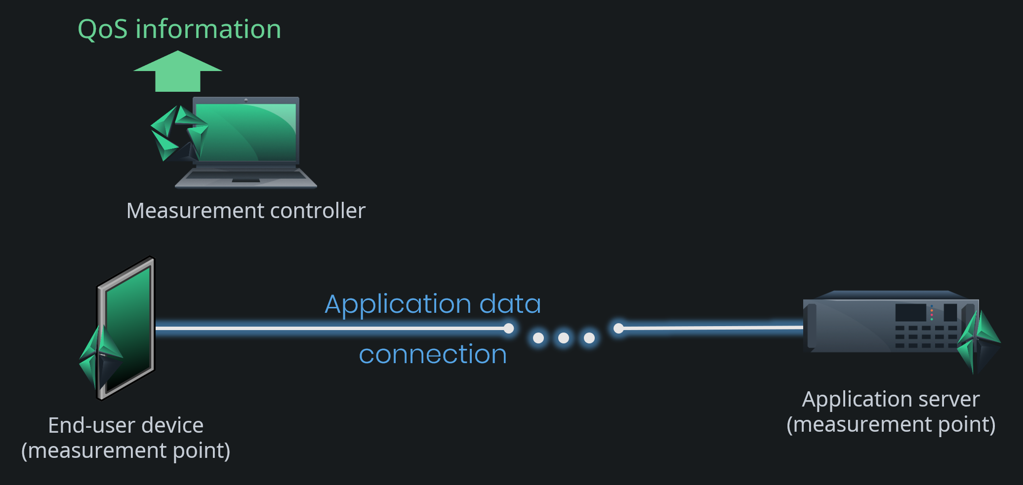
This topology is the simplest one, and it is very common. The communicating end devices also act as measurement points. Thus, the results give the most accurate view of how the measured interesting application traffic performs end to end, i.e., the QoS level the network path between the devices gives to the application.
Parameterizing such measurement is straightforward. Just tell Qosium that the measurement nodes are at endpoints, and Qosium calculates almost all the other parameters automatically. Even the packet filter is automatized. The automatic filter will include all the traffic between the end devices. If you are interested only in specific traffic flows, tune the filter manually.
2.2. One End-Point #
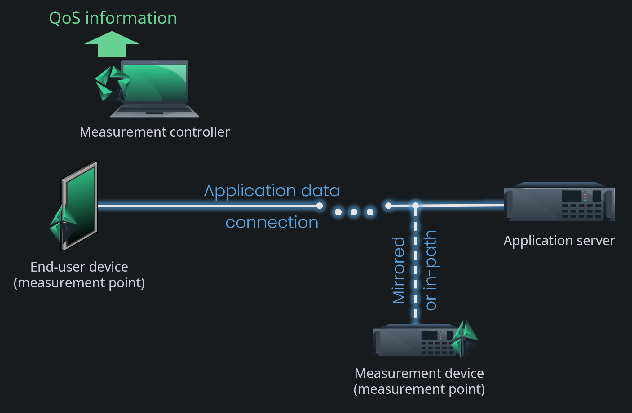
Sometimes it is not possible to install Qosium Probe in the end devices on both ends. Also, it might be that you are interested in the performance of your own network part, not the whole end-to-end part. As a result, we get a measurement topology, where one measurement point is in an end device, but the other is in the middle of the application traffic path. In some cases, the other point is not directly in the path but located in an external device, to which the traffic of your interest is mirrored for measurement purposes.
This measurement topology is still sufficiently easy to parameterize. The key difference, when compared to the end-to-end topology, is that automatic filtering is not possible. Thus, you must always set the packet filter manually in this topology option.
2.3. On Traffic Path (in an Active Network Component) #
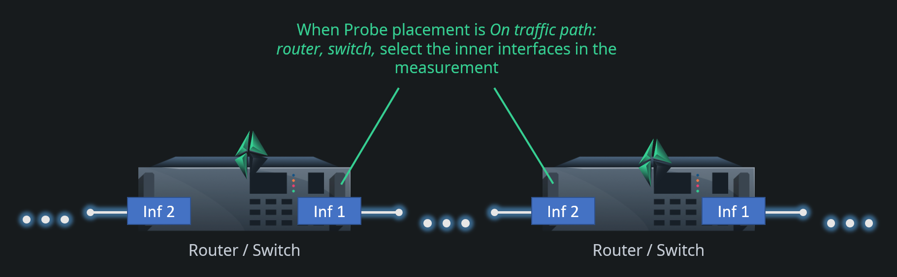
What if you are interested only in the quality of some specific part somewhere in the network? In this case, none of the measurement points are located in end devices but within the network path between the communicating devices. When Qosium Probes are installed on traffic path in an active network component, parameterization is still straightforward. By an active network component, we mean a device that participates in traffic handling actively, e.g., a router or a switch. Parameterization is similar to that of the One end-point topology. The main difference is in the placement parameters, naturally.
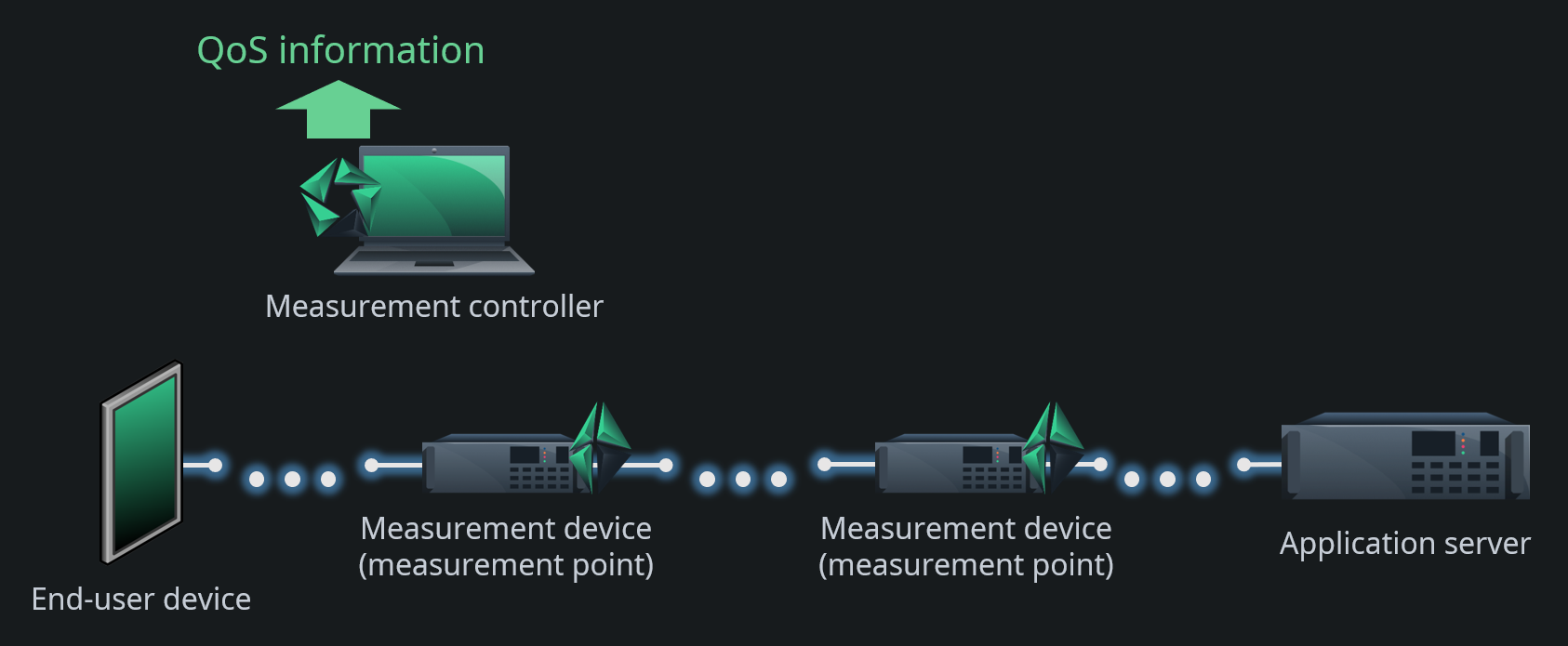
In this scenario, you need to pay some attention to the devices: how they operate and how they are connected. For example, a network bridge is considered as a passive device, and parameterized accordingly. The reason is that MAC addresses are used to define the flow directions in this mode, but it does not work for passive devices that just let the traffic through untouched like a network bridge does.
Also, be careful when selecting the network interfaces in this kind of a scenario. You need to select the inner interfaces between the measurement points as shown in the figure below. Again, this has to do with MAC addressing. If you, however, want to measure over the devices, i.e., to use the outer interfaces, e.g., to include the switching/routing delay in the measurement, you need to consider the scenario as your measurement point would be a passive network component.
 If the traffic or the network interfaces are such that there is no L2 addressing, you need to set the Sender parameters manually
2.4. On Traffic Path (in a Passive Network Component) #
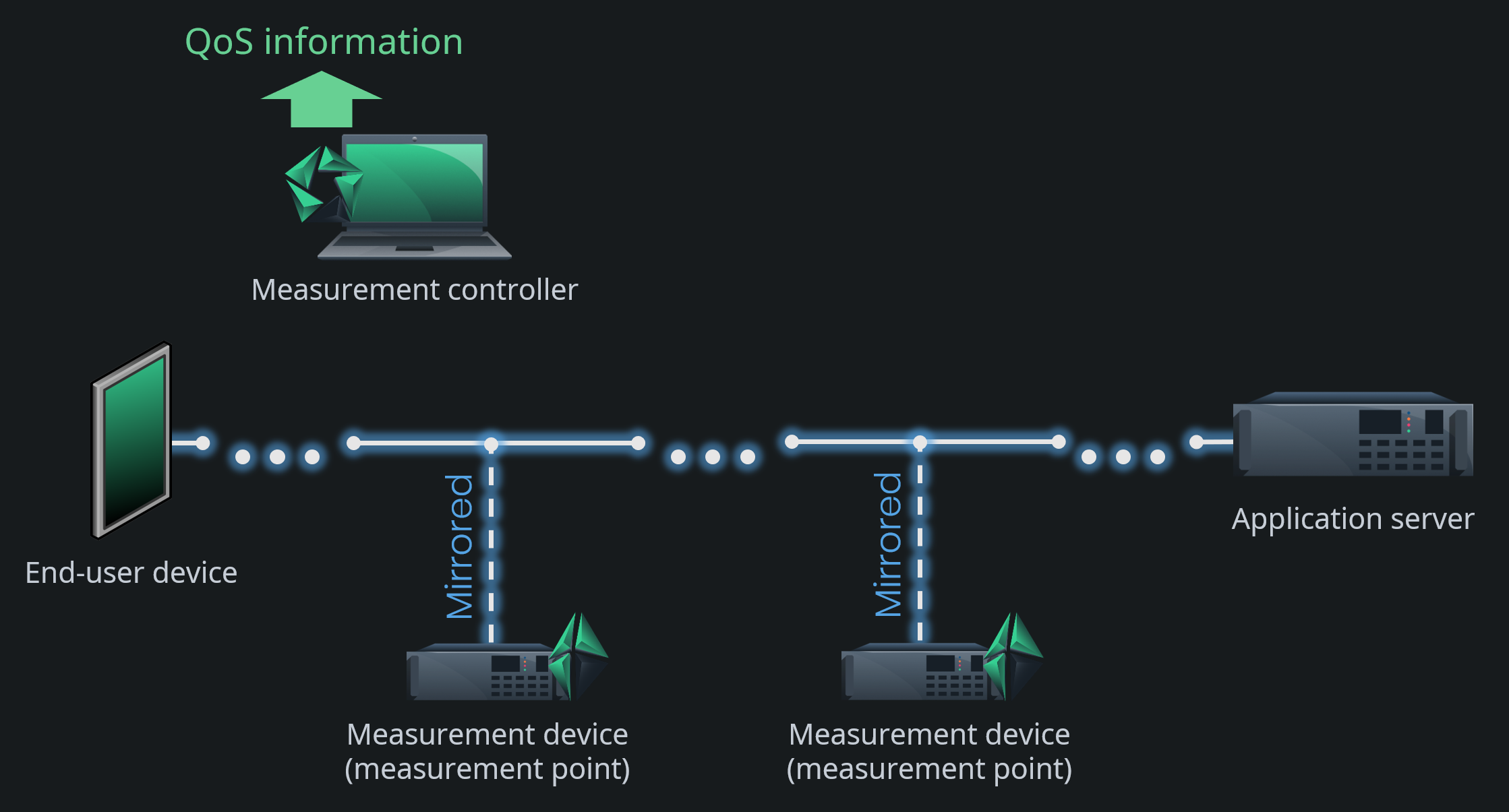
Consider a measurement topology like the previous one, but where Qosium Probes are installed on passive network devices. By this, we mean devices that do not actively modify traffic but try to let traffic through unmodified. The most obvious example of this kind of setup is a network tap that passively copies network traffic and forwards it to a separate measurement device. Another example is using port mirroring of a switch to forward the measured traffic to an external machine. A switch itself is an active network component, but now the measurement is not run in the switch. In addition, most network bridges fall into this category. Straightforward as such, but regarding passive measurement, the problem is that there is no longer accurate information available considering the direction of the traffic. Therefore, you need to give the measurement system hints considering the direction of the traffic. To do this in Qosium, set the Sender address parameters manually in this case. Also, you cannot use the automatic packet filter in this topology.
This is the most laborious basic topology in terms of parameterization. Should there be a NATNetwork Address Translation
A technique for remapping an IP address space between the measurement points, you get a couple of parameter options more to do, but that is the most complex parameterization you can ever get in Qosium.
3. Network Interface Selection #
Modern devices typically integrate multiple network interfaces. Consequently, it is essential to select the correct ones for the measurement. Choosing an incorrect interface is one of the most common mistakes in the measurement setup.
Consider the figure below. If you wish to measure the network path between the end-user device and the router, you need to select interface 1 in the end-user device and interface 2 in the router. By selecting interface 2 in the end-user device will show all packets coming from the router as lost. Besides, all packets received by the router are calculated as SINFSent Information Not Found
This is a special statistic, meaning that a packet was received but was not indicated sent on the other end. as their sending is not registered in the end-user device. If you select interface 1 in the router, the measurement will succeed, but the measured QoS includes the routing process performance. Of course, if that is what you want, then the interface selection is correct.
Since Qosium is a multi-thread solution, you can carry out interesting measurements by using only a single Probe. Consider if you perform a two-point measurement in the figure’s router. While the same Qosium Probe acts as the Primary and the Secondary measurement point, select different interfaces to them. For example, set the Primary measurement point to listen interface 2 and the Secondary to interface 1. What you get now with this kind of setup is the internal routing performance of the device. Moreover, since both of the measurement points are in the same device, the clock synchronization is ideal. You will be able to measure very accurate delay performance up to the microsecond level. Only the router’s internal process priorities cause some minor inaccuracies.

4. Dealing with Tunnels #
A two-point passive QoS measurement works only if the packet context in both ends matches. Consequently, if there is a tunnel, pipe, or similar within the network path, the measurement point selection needs some attention.
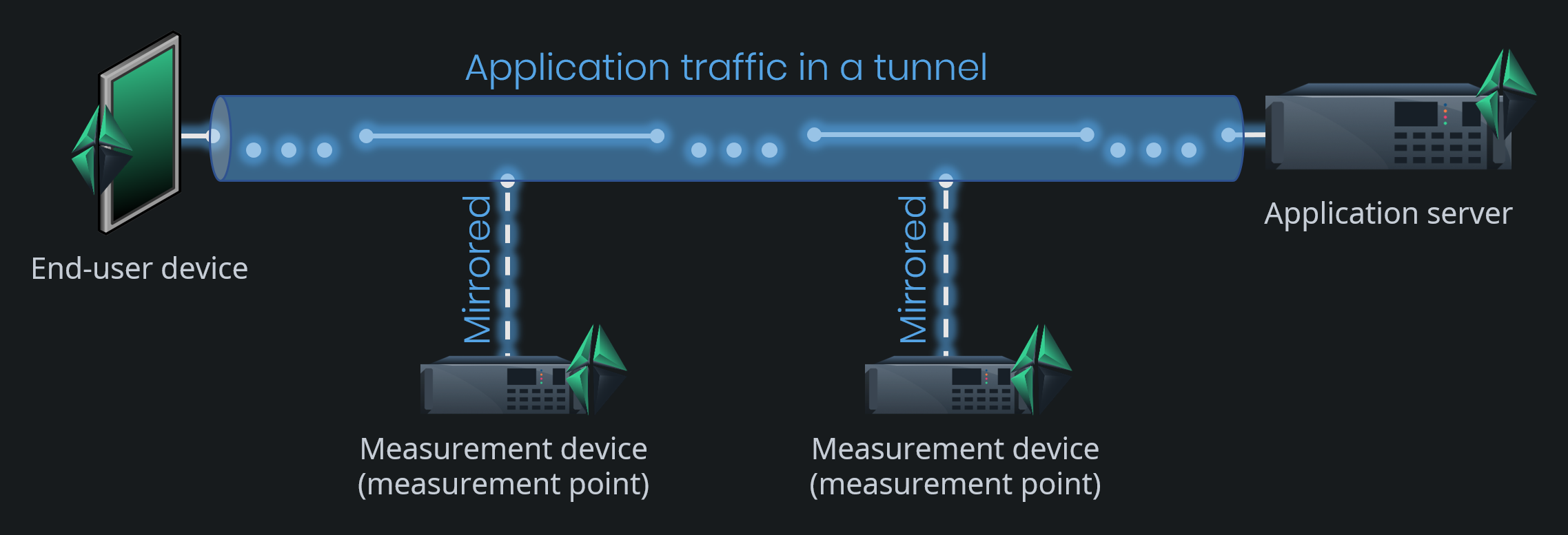
Consider the figure below: the application traffic is flowing inside a tunnel (e.g., VPNVirtual Private Network
A technique to provide a secure tunnel over a public network. between an end-user device and an application server. A successful QoS measurement can be made end-to-end since both of the end-points lie outside the tunnel. Also, a successful measurement can be carried out between the off-path external measurement points since they both see only the tunneled traffic. However, a measurement from the end-user device to one of the external measurement points, generally, cannot be made since the packet context does not match. The end-user devices see the packets as they are, but the external measurement points see tunneled packets, often encrypted.
There are some exceptions, however, of tunneling protocols over which Qosium measurements are possible:
- MPLSMultiprotocol Label Switching
A routing technique in telecommunications networks that forwards data based on short path labels rather than long network addresses.- Qosium is equipped with functionalities to dig the original traffic flows inside a non-encrypted MPLS tunnel.
- However, some Pcap-versions can have problems to filter inside an MPLS tunnel. Without filtering, a QoS measurement will very likely fail. Of course, it is possible to perform manual low-level filtering based on individual protocol fields, but this gets easily laborious.
- GTPGPRS Tunnelling Protocol
A group of IP-based communications protocols used to carry data within GSM, UMTS, LTE and 5G NR radio networks.- Kaitotek has made a Linux kernel module that can extract the traffic inside a GTP tunnel, enabling it to be measured as such.
- Please ask Kaitotek support or sales about the QGTPR module.
5. Direction of Traffic and Senders #
Consider the end-to-end measurement topology: which way is the traffic flowing? Determining that is very easy since the measurement points are the same devices that generate the traffic: just compare device addresses to the traffic addresses. But, what about in a topology where the measured traffic is mirrored to external measurement devices? You could think that it is obvious. Just look at the topology. But, Qosium does not see the topology as we do. Instead, Qosium Probes only see the device in which they run and now a single NIC through which all the traffic is coming in. The traffic is not originated, nor meant to that node, so there is no information left to tell which way the traffic was flowing in its original point of capture. Because of the two-point measurement, the measured one-way delay could be used to tell the direction, but as there can be clock synchronization errors, it cannot be trusted to cover all cases.
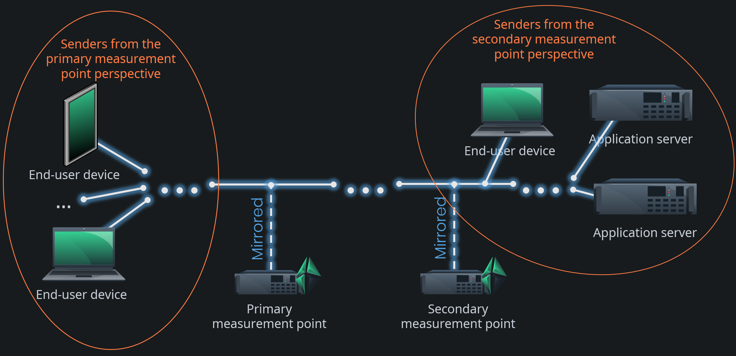
Therefore, there are special cases where you need to tell Qosium by extra parameters which way the traffic is flowing. This is done by the Sender parameters. You tell Qosium Probe, who, from its perspective, are the senders, i.e., the devices who send traffic towards the other measurement point. See the figure below. If, for example, one end-user device on the left-hand side of the figure is communicating with an application server on the right, the end-user is a sender from the Primary measurement point perspective. Then, the application server is a sender from the Secondary measurement point perspective. That you need to tell Qosium with parameters. It is typically enough to determine the senders only in one measurement point and then use the inverse definition (in Qosium Scope: According to primary/secondary Probe) in the other.
Qosium allows setting senders as individual addresses or as address range by using a mask. Senders can be set independently for IPv4, IPv6, and MAC addresses.
Glossary >
Network Address Translation
A technique for remapping an IP address space
QoS Measurement Control Protocol
Kaitotek's proprietary protocol for controlling measurements and gathering measurement results.
QMCP is a protocol made by Kaitotek to optimize QoS measurement control communications. TCP is used in the transport layer (currently), but QMCP controls its sessions. All Qosium products use QMCP.
Network Address Translation
A technique for remapping an IP address space
Sent Information Not Found
This is a special statistic, meaning that a packet was received but was not indicated sent on the other end.
In a way, this is negative packet loss, which, of course, is an absurd concept as such. Therefore, the continuous appearance of SINF values is often an indication of incorrect parameterization of the measurement. For example, if the packet filter is set too loose, traffic can arrive at the measurement point from other sources than those seen by the peer measurement point. This statistic can also grow occasionally if the QMCP connection between the Probes has too low QoS to stay synchronized with the measurement’s pace. SINF can, however, also occur naturally if the measured traffic content is somehow changed (consider, e.g., video transcoding) between the network path of the measurement points. In that case, the sending side measurement point sees its packets as lost, while the receiving side sees SINF.
Virtual Private Network
A technique to provide a secure tunnel over a public network.
Multiprotocol Label Switching
A routing technique in telecommunications networks that forwards data based on short path labels rather than long network addresses.
GPRS Tunnelling Protocol
A group of IP-based communications protocols used to carry data within GSM, UMTS, LTE and 5G NR radio networks.